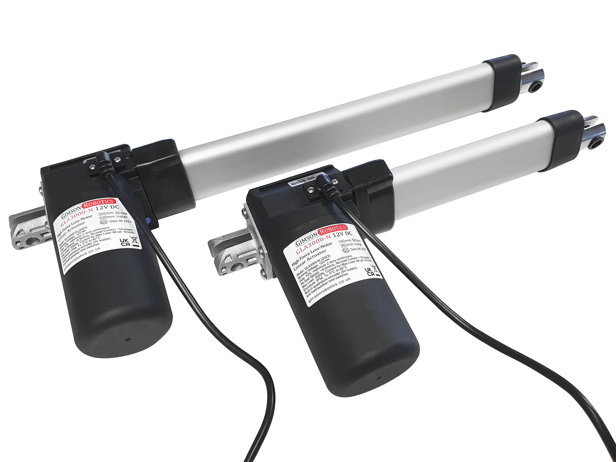
GLA3000-N 24V DC Low-Noise Linear Actuator with Encoder

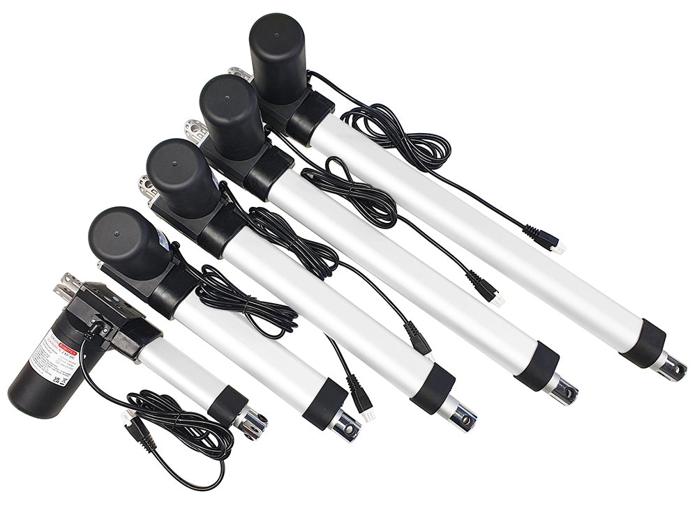
The GLA3000-N is a high force (up to 3000N, 305kg) and low noise linear actuator, available in five different stroke lengths of 100mm (4"), 200mm (8"), 300mm (12"), 400mm (15 3⁄4"), 500mm (19 11⁄16"). It is designed to run at 24V DC, and it features a built-in quadrature encoder enabling position tracking and synchronisation when used with an appropriate controller.
The travel speed is 9.5mm/s under no-load, reducing down to 6mm/s at the full rated 3000N load. Typical applications include maintenance and access hatches, adjustable tables & work surfaces.
Availability: IN STOCK
SKU: GLA3000-N-24-100
Couldn't load pickup availability
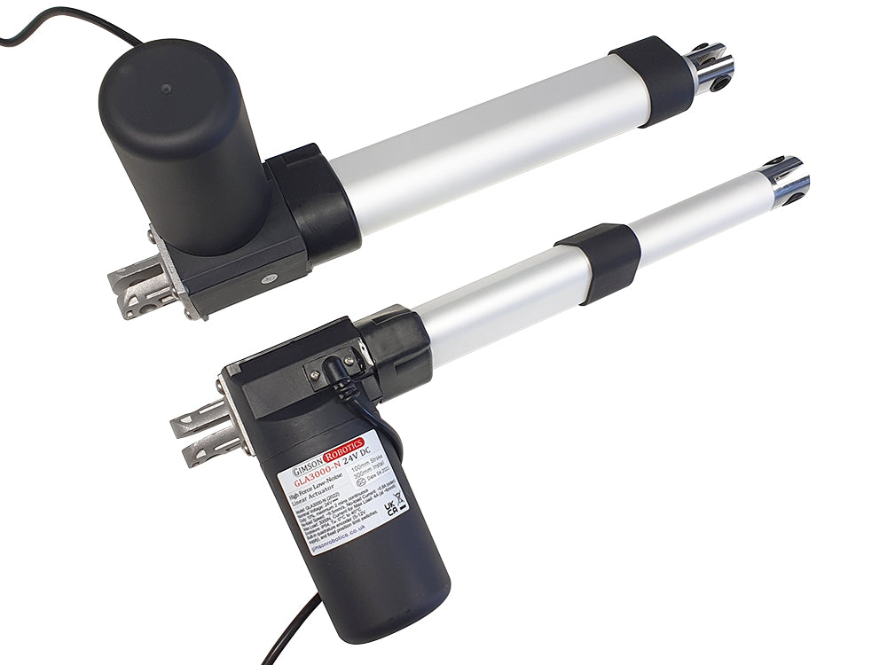
GLA3000-N (24V)
This model of actuator is a useful size for applications such as adjustable furniture, large windows, and lifting assemblies. The powerful and yet quiet 24V motor may be run from either a 24V battery, or from the mains via an AC to 24V DC adapter.
Sturdy stainless steel mounting brackets are available, designed specifically for this model of actuator.
Integrated Encoder, for position detection and synchronisation
The actuator has a hall-sensor based quadrature encoder built-in to the motor. The encoder is powered by two of the six cores of the main cable (+Vcc Red, -GND Black) and accepts a supply voltage of 5V. It has a dual-channel output (channel A Yellow lead, Channel B Orange lead), with each channel generating 15.6 pulses per millimetre of travel (3 complete pulses per motor revolution). One of the channels is out of phase with the other, as such it is possible to tell both the speed (from pulse frequency) and direction (by reading the pulses of one channel and comparing it to the other) of the motor. The nature of the signals that are generated is illustrated below. Given a maximum no-load travel rate of 9.5mm/s for the 24V motor (when run at 24V) the maximum pulse frequency would be ~148.2Hz per encoder channel (the frequency rate would be greater than this if your controller is counting all rising/falling edges as opposed to only HIGH/LOW signal state changes). When used with the appropriate controller the encoder signals can be used for positional control with much greater accuracy and consistency than potentiometer-based actuator feedback systems.

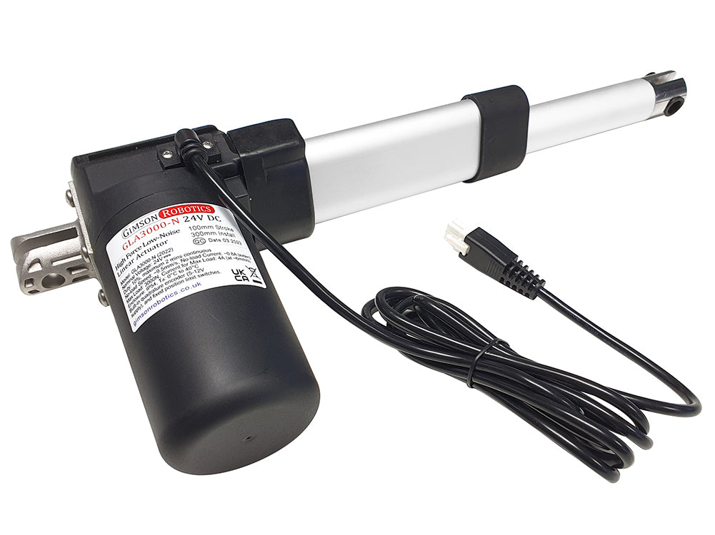
Leads & Connector Options
The actuator comes with a 2m long PVC-insulated lead as standard, with a Male 6-pin connector (4.2mm pitch, 3x2 format, latched) on the end (see below for connector image). The cable has six internal cores: Blue and Brown (to the motor, thicker wires), Red and Black (positive and negative power to the hall sensor encoder circuit, thinner wires), Yellow, and Orange (outputs from the encoder, channel 1 and channel 2, also thinner wires). The connections are illustrated in the below diagram which also shows the limit switch circuit inside each actuator, in series with the brown and blue motor leads.
Please see the Electrical product section (link above) for Female 6-pin adapters and extension leads, which are available seperately. If you have a custom lead length or connector requirement, please contact us.


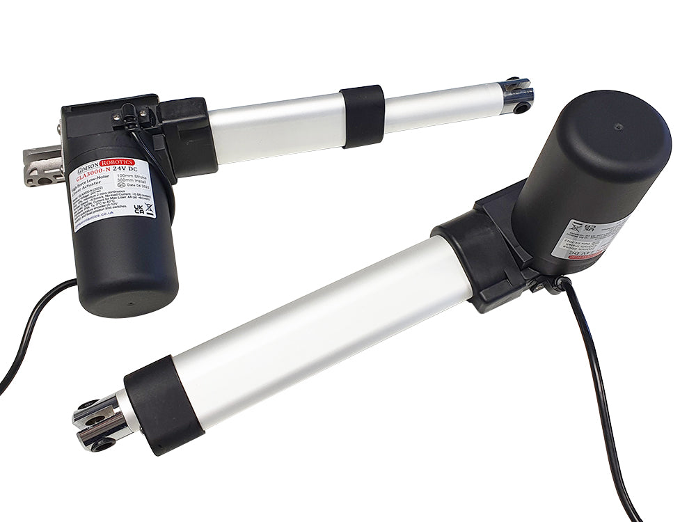
Output Orientation

User Advice
 Device Safety
Electric actuators such as this model are low-voltage electromechanical components that are used in a wide variety of different applications. It is important that the safety of each installation is assessed according to its own requirements, construction, end user and environment. Please see a list of design principles on page 3 of the actuator reference sheet (PDF), which we strongly recommend that you adhere to in your end-application design.

A PDF copy of the actuator datasheet can be downloaded here.
Operating Characteristics

Maximum load: 4A. Do not apply power to the actuator if the load exceeds the maximum rating, this would void the warranty and be likely to damage the gearbox, bearings or motor. If using overcurrent detection to protect the motor, ensure that this is sensitive enough to react quickly to an overcurrent event.
< 52dB under full-load
Actuator Build Detail
(click on image to expand)

| 100mm stroke: 300mm | 200mm stroke: 400mm |
| 300mm stroke: 500mm | 400mm stroke: 600mm |
| 500mm stroke: 700mm |
Enclosure rated to IP54, only suitable for outdoor use if protected (fully shielded) from running water and high levels of condensation.


| 100mm stroke: 2180g | 200mm stroke: 2450g |
| 300mm stroke: 2730g | 400mm stroke: 3000g |
| 500mm stroke: 3280g |
If you have any questions about this item, including requests for bulk-pricing information, then please contact us.
Related Products
GLA3000-N 12V DC Low-Noise Linear Actuator with Encoder
from £106.10 £123.78 inc VAT
A high strength electric actuator with built-in encoder to enable synchronising and position control
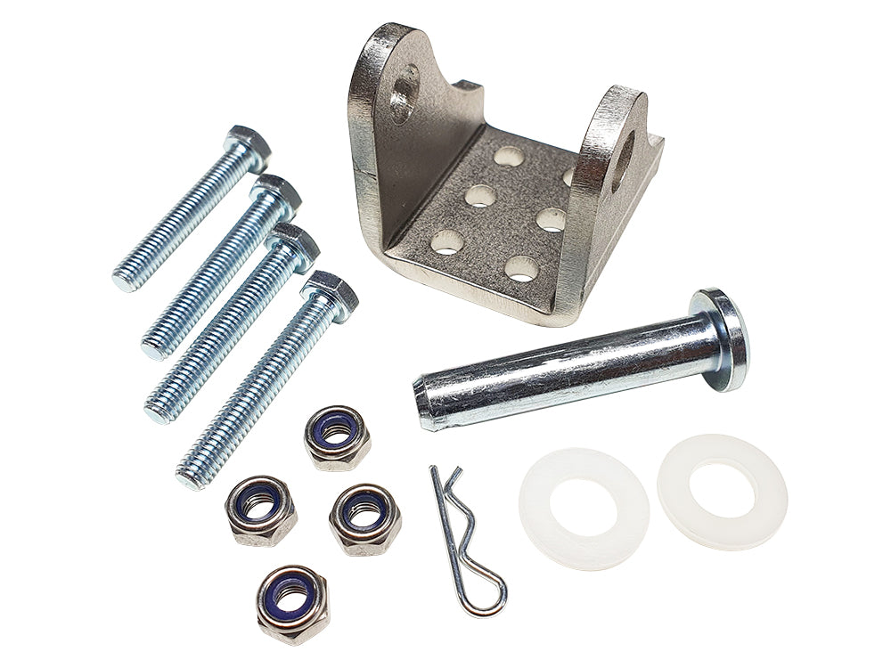
Heavy Duty 5mm A4 Stainless Steel Actuator Bracket, 10mm Pin
from £9.00 £10.50 inc VAT
Sturdy 314 stainless steel bracket folded from 4mm thick laser cut plate, ideal for the GLA4000-S or GLA3000-N models of actuator
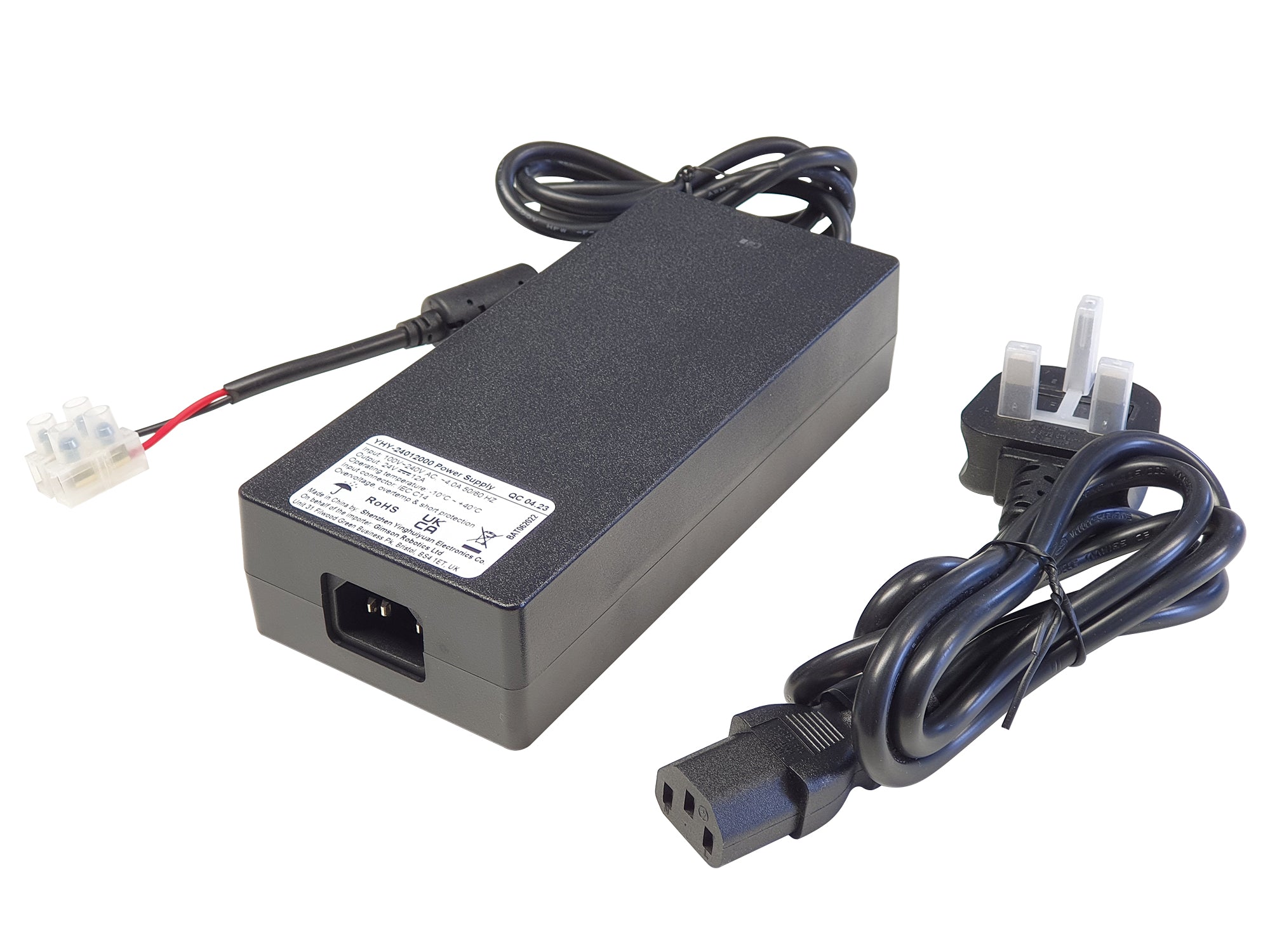
AC to 24V DC 12A Power Supply/Adapter for Motors & Actuators YHY
£62.40 £72.80 inc VAT
Heavy duty yet silent power adapter, designed for use with DC electric motors and actuators
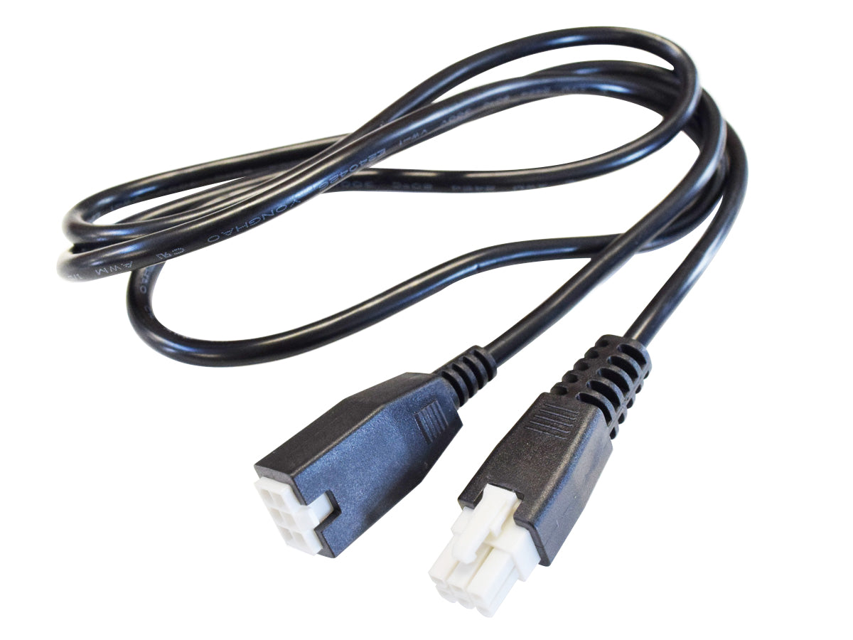
6-Pin Male to Female Extension Cable 1.35m, for Actuators with Encoders
£4.90 £5.72 inc VAT
An extension cable that interfaces with many of our 6-pin actuator cable sets, for when your system needs to reach a little futher