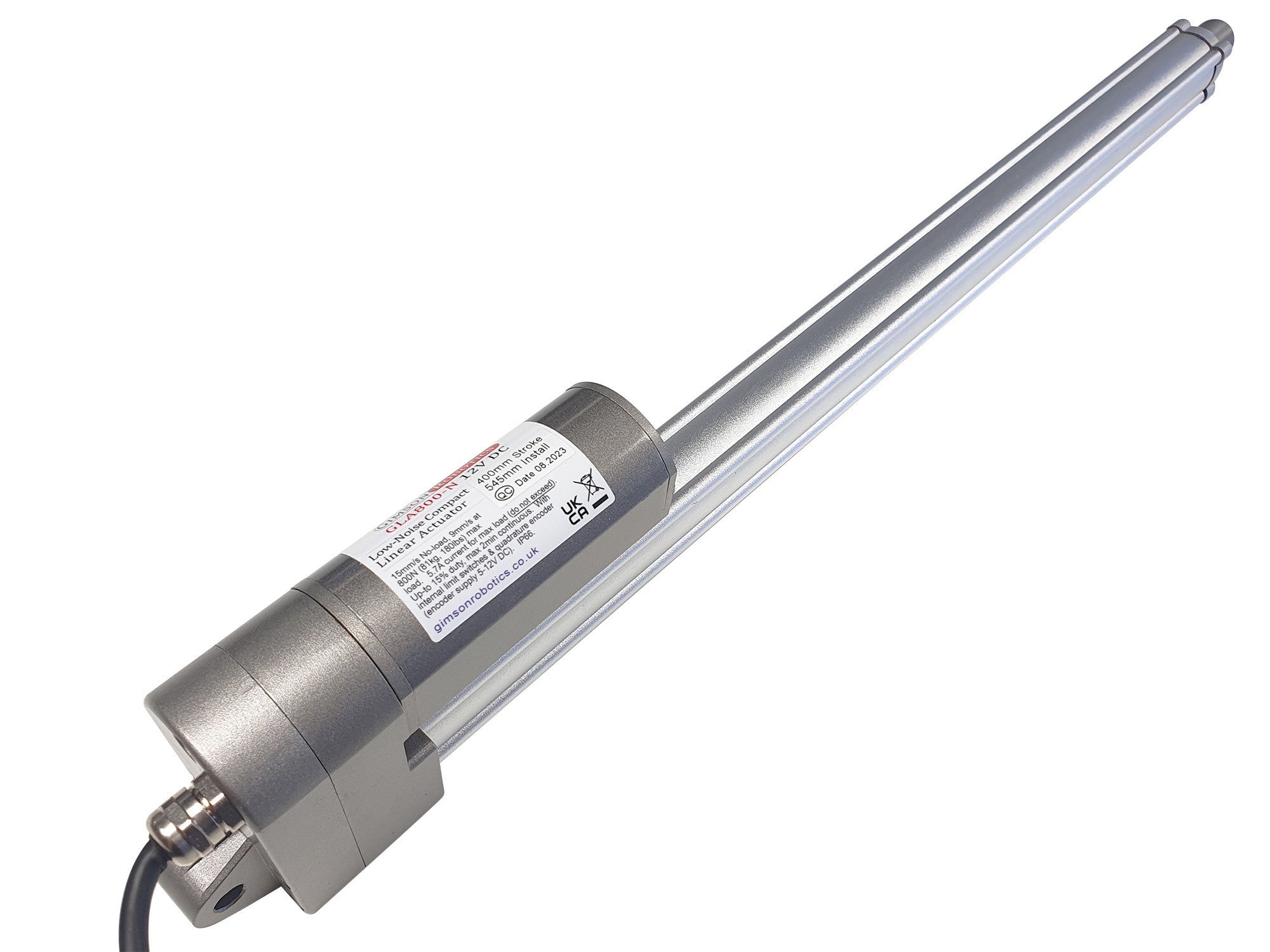

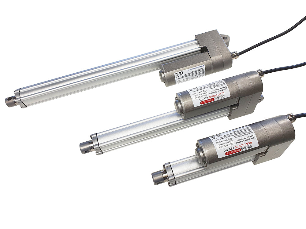
GLA800-N 12V DC Low-Noise Compact Linear Actuator

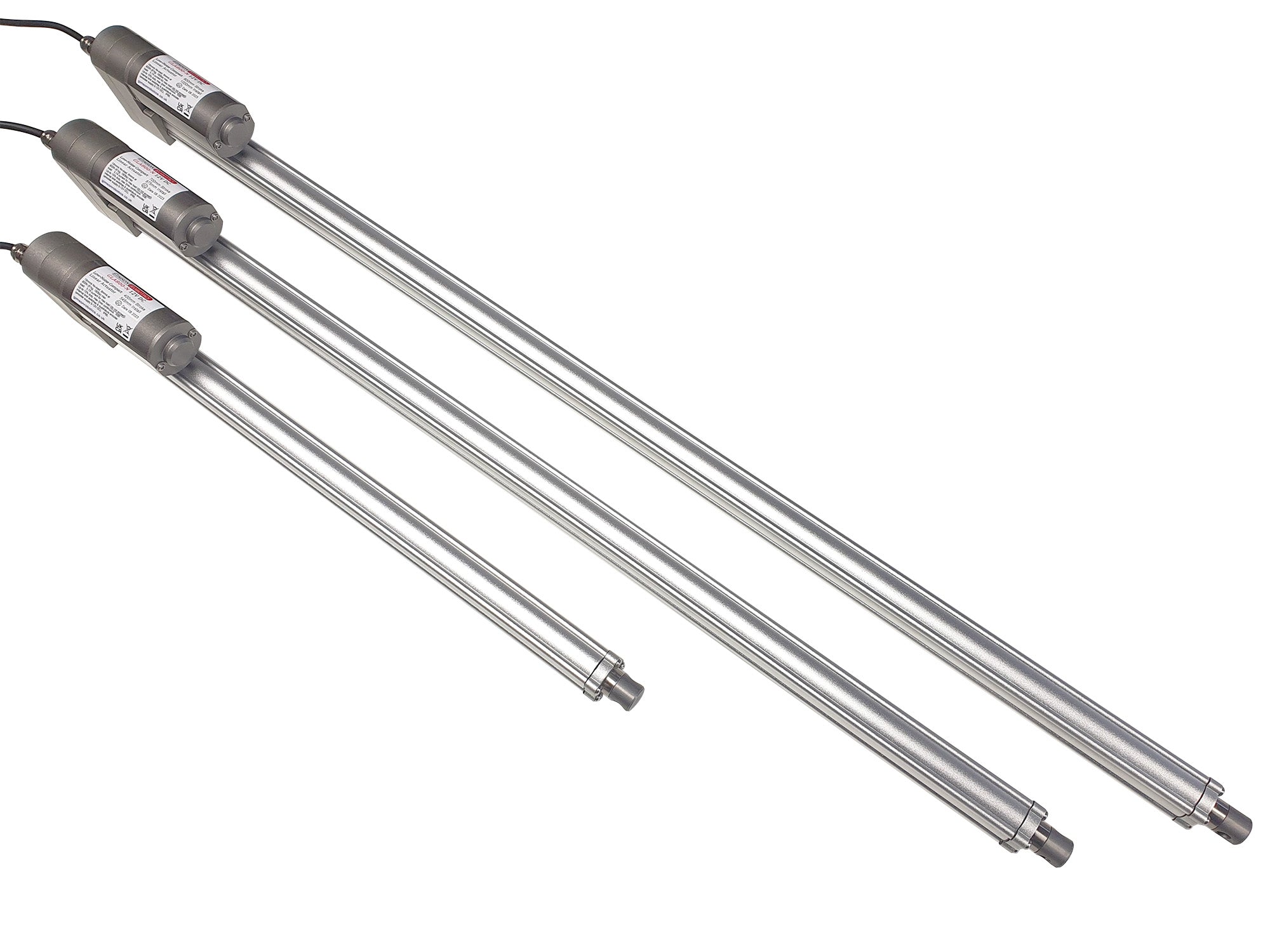
The GLA800-N is a compact-bodied, low noise actuator, available in relatively long travel lengths of 400mm (15.75"), 700mm (27.6"), and 800mm (31.5") stroke. A built-in quadrature encoder allows the actuator travel speed (and position) to be accurately measured, which means that two (or more) of the actuators can be synchronised when paired with a suitable controller.
Typical applications include automating windows and skylights, as well as access hatches and furniture. Each actuator may provide a pushing or pulling force of up to 800N (81kg, 179lbs) and offers a travel speed of up to 14.5mm/s.
Availability: IN STOCK
SKU: GLA800-N-12-400
Couldn't load pickup availability
GLA800-N (12V)
The GLA800-N model shares the same compact motor and outer body of the higher-capacity and slower-travelling GLA1500-N model, but with a different lead screw size for faster travel.
As with most of our stock actuators this model has built-in limit switches at the ends of travel, meaning the actuator should stop automatically at the fully retracted and the fully extended positions.
Integrated Encoder, for position detection and synchronisation
The actuator has a hall-sensor based quadrature encoder built-in to the motor. The encoder is powered by two of the six cores of the main cable (+Vcc Red, -GND Black) and can run from a DC supply of between 5-12V. It has a dual-channel output (channel A Yellow lead, Channel B White lead), with each channel generating 17.4 pulses per millimetre of travel (4 pulses per motor revolution). One of the channels is out of phase with the other, as such it is possible to tell both the speed (from pulse frequency) and direction (by reading the pulses of one channel and comparing it to the other) of the motor. The nature of the signals that are generated is illustrated below. Given a maximum no-load travel rate of 14.5mm/s for the 12V motor (when at 12V) the pulse frequency may be up to 253Hz per encoder channel (the frequency rate may be greater than this if your controller is counting all rising/falling edges as opposed to only HIGH/LOW signal state changes). When used with the appropriate controller the encoder signals can be used for positional control with much greater accuracy and consistency than potentiometer-based actuator feedback systems.

Leads & Connector Options
The actuator comes with a 2m long PVC-insulated lead as standard, this has six internal cores: Blue and Brown (to the motor, thicker wires), Red and Black (positive and negative power to the hall sensor encoder circuit, thinner wires), and White and Yellow (outputs from the encoder, channel 1 and channel 2, also thinner wires). If you are only running a single actuator (don't require synchronised control) and don't need position/speed feedback then you can connect directly to the brown and blue motor leads and ignore the others. The connections are illustrated in the below diagram which also shows the limit switch circuit inside each actuator, in series with the brown and blue motor leads.
Options are provided above for us to add a 6-pin connector (4.2mm pitch, 3x2 format, latched) onto the actuator lead, bringing the total lead length to either 1m or 2.5m. If you have a custom lead length or connector requirement, please contact us.


User Advice
 Device Safety
Electric actuators such as this model are low-voltage electromechanical components that are used in a wide variety of different applications. It is important that the safety of each installation is assessed according to its own requirements, construction, end user and environment. Please see a list of design principles on page 3 of the actuator reference sheet (PDF), which we strongly recommend that you adhere to in your end-application design.

Operating Characteristics

Maximum load: 5.7A. If using overcurrent detection to protect the motor, ensure that this is sensitive enough to react quickly to an overcurrent event.
< 50dB under full-load
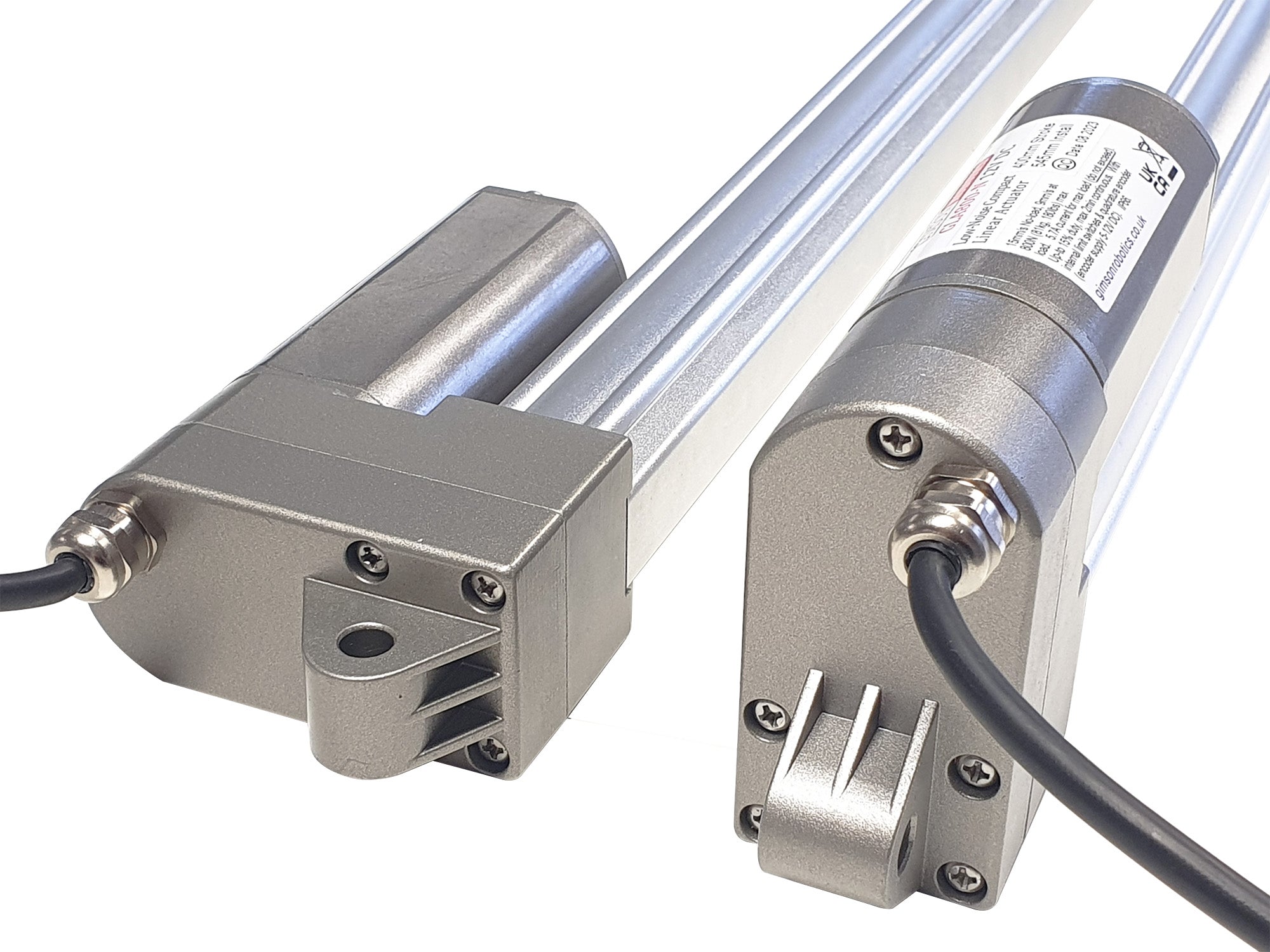
Actuator Build Detail
(click on image to expand)

| 400mm stroke: 545mm |
| 700mm stroke: 875mm |
| 800mm stroke: 1000mm |


| 400mm stroke: 1910g |
| 700mm stroke: 2550g |
| 800mm stroke: 2760g |
If you have any questions about this item, including requests for bulk-pricing information, then please contact us.
Related Products
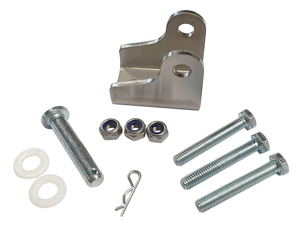
Stainless Steel A4 3mm Actuator Clevis Bracket, 8mm Pin
from £6.00 £7.00 inc VAT
Folded laser-cut stainless steel bracket for actuators with a 8mm mounting hole size such as the GLA1500-N or GLA800-N models
GLA1500-N 12V DC Compact High Force Low-Noise Actuator
from £106.70 £124.48 inc VAT
A high quality medium-sized actuator with a dual-worm stage gearbox ensuring very low noise levels when running
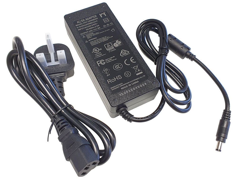
AC to 12V DC 8A Power Supply/Adapter for Motors & Actuators YHY
£24.60 £28.70 inc VAT
A compact and high-efficiency power adapter, specially designed for use with DC electric motors and actuators
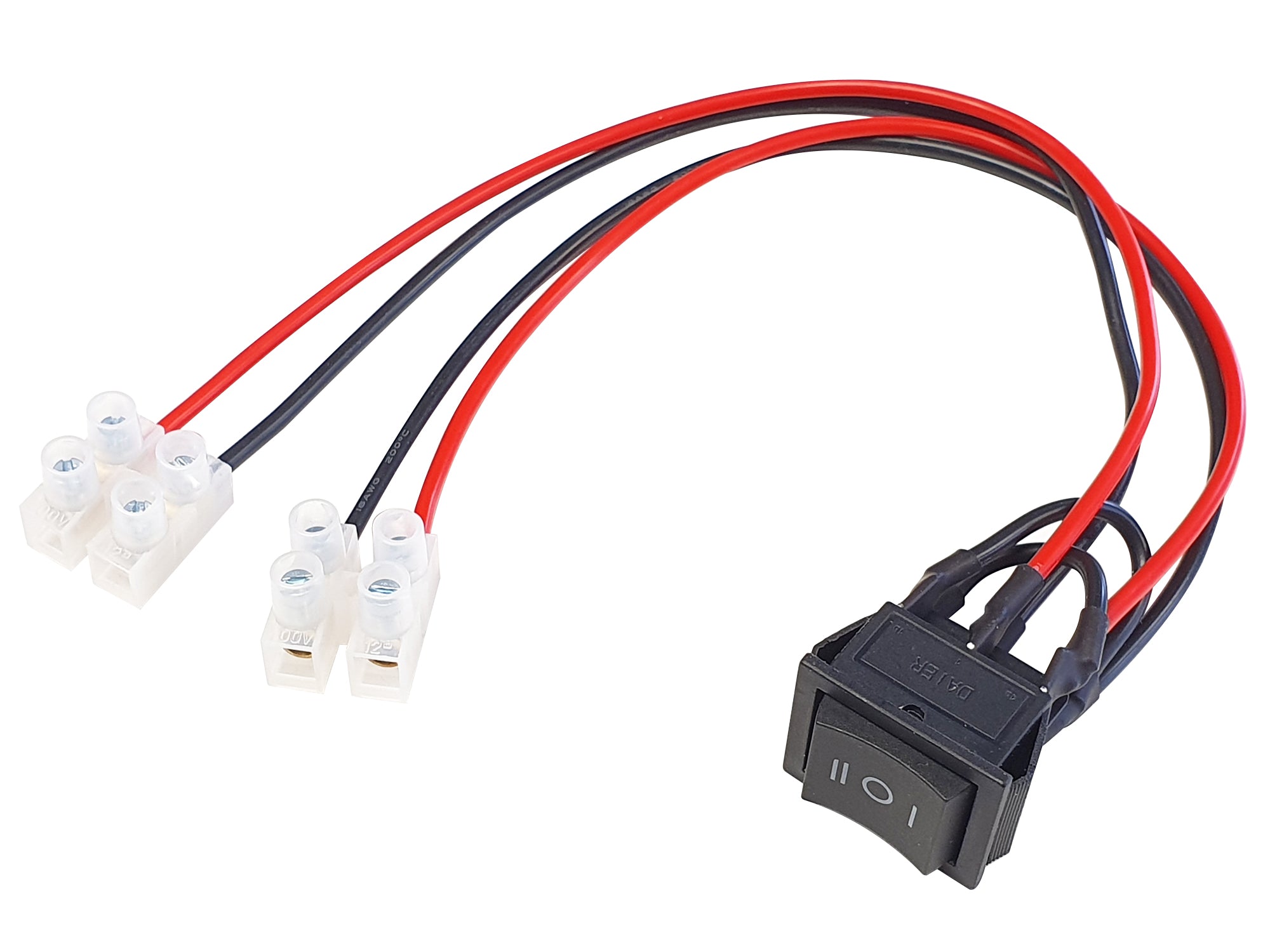
Rocker-Switch Harness for DC motors, 15A Version
from £14.80 £17.27 inc VAT
Easy to use wired control device, for controlling the direction of DC electric motor and actuators. Available in Latching or Momentary versions.