This controller is the culmination of many years of experience in developing motor and actuator control solutions. It provides a simple and reliable means of operating individual electric actuators bidirectionally, whilst adding many adjustments and protections that aren't available on more-basic controllers. Please click the link on the left to
download a PDF copy of the device instructions, or see main features described below:
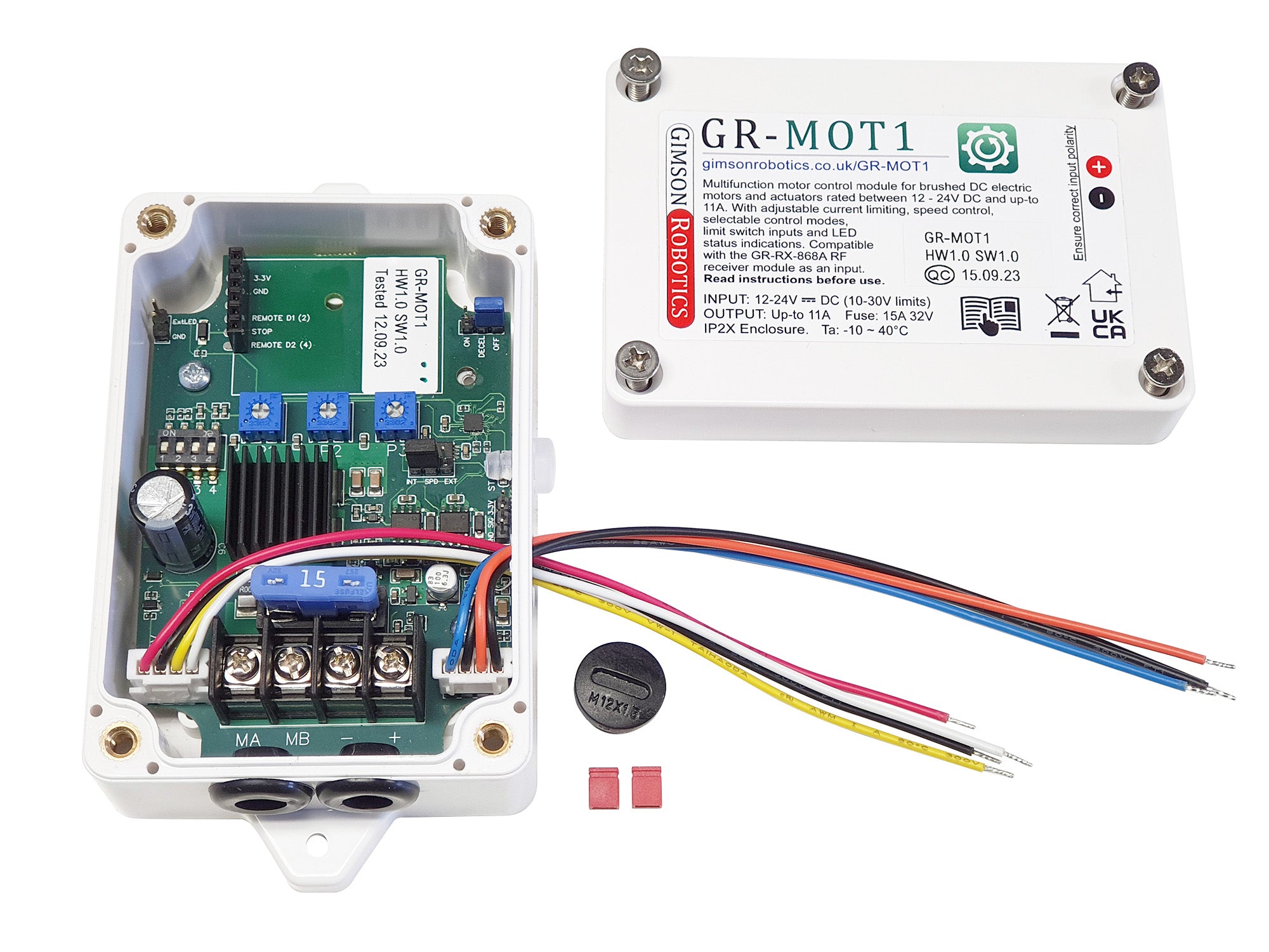
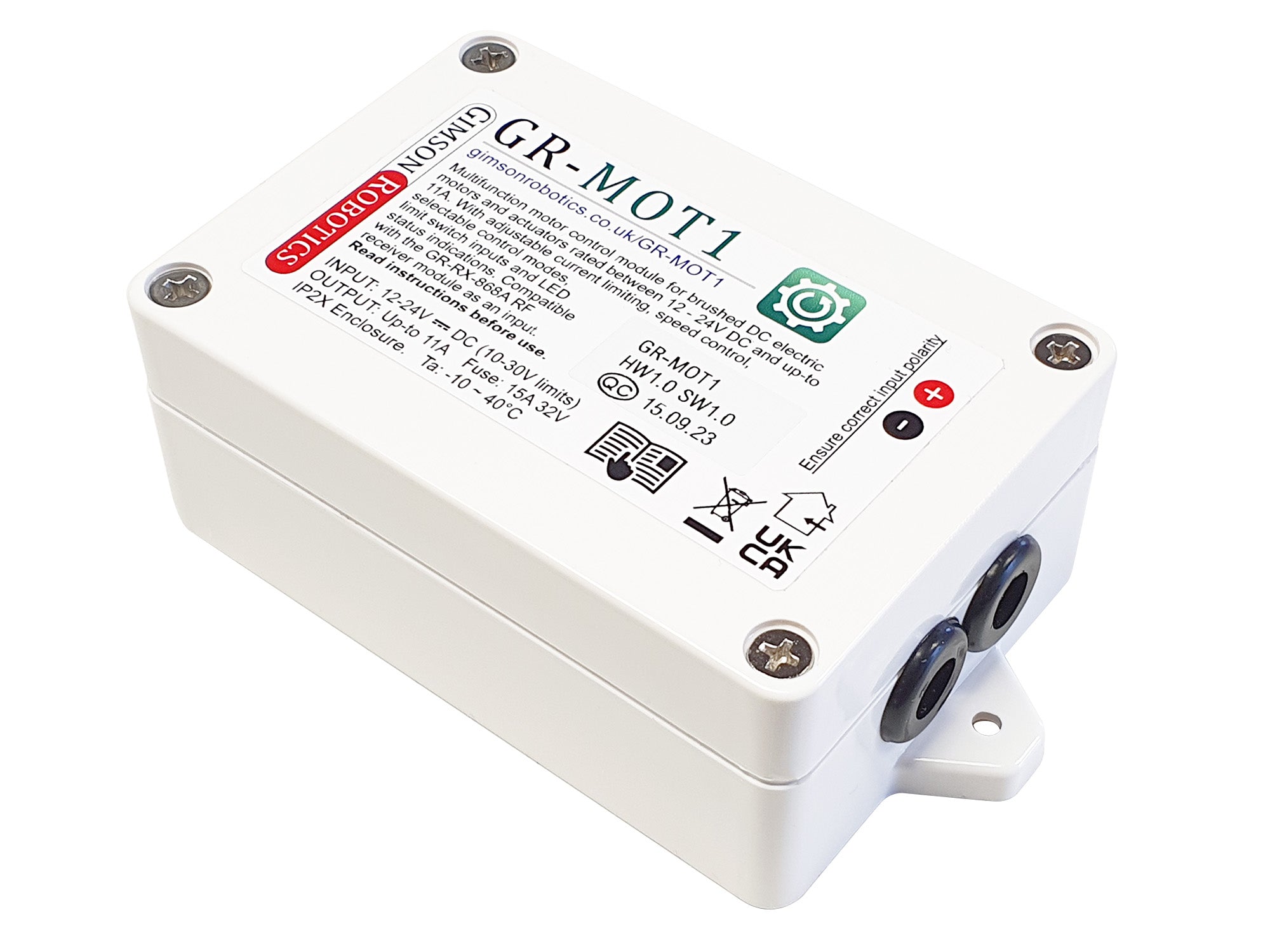
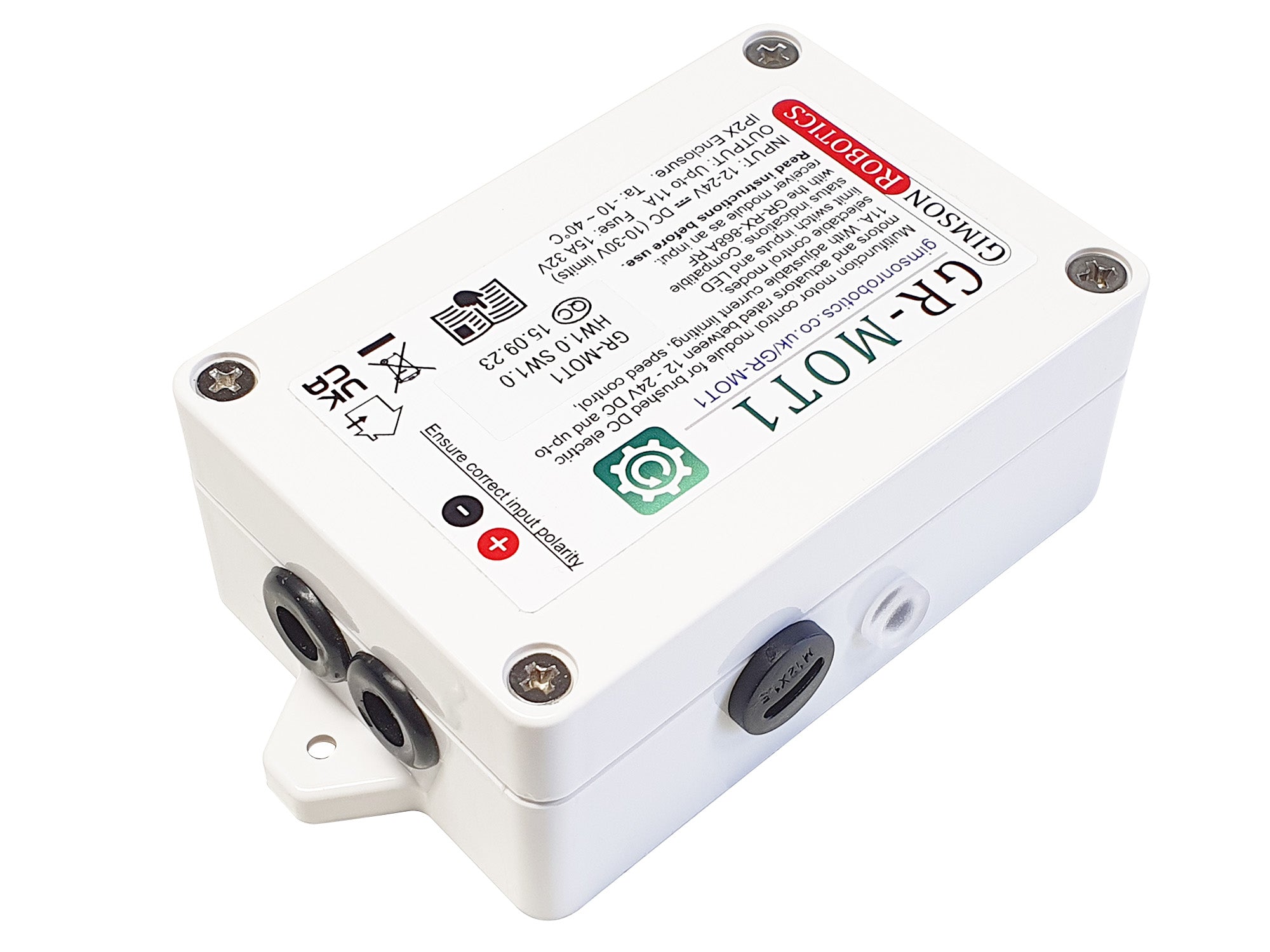
Enclosure, wired control
The controller is supplied mounted in a tough plastic enclosure (100 x 68 x 40mm main body size) with two grommeted holes at one end for connection, via four screw terminals on the board, to a power source of between 12 - 24V DC and to a load (a brushed DC motor or actuator of up-to 11A steady load, as limited by the on-board overcurrent protections). For basic wired operation you simply need to connect control switch(es), via the included 4-wire connector lead, between '3.3V' and 'D1', or between '3.3V' and 'D2', to achieve bidirectional control. A dedicated 'STOP' switch input is also available via this wired connection.
Control logic
Control logic can be independently toggled between momentary ('while pressed') and latching ('single-press') for the wired and the optional remote control inputs, with momentary control being the default mode for both. If you have selected a remote control option, or if you later add a receiver module (which are plug-in accessories), bear in mind that wired switch inputs to the controller override remote inputs.
Solid state control, with speed adjustment
The output is switched by low-resistance MOSFETs, extending the lifetime of the device when compared with relay-based controllers. Output speed (PWM duty, switched at 19.6kHz) can be adjusted between 20-100% either via the dial P3 on the board, or via an external potentiometer for which the connections are available (GND, SIG, 3.3V) near the status LED on the board. This speed setting may be adjusted mid-cycle, while the output is active. The default output speed setting is 100%.
A soft-start feature (800ms of acceleration applied automatically at the start of each movement) helps to minimise the current spike from a motor at the start of a movement, allowing more-sensitive power supplies to be used with the controller and also reducing the mechanical stresses on an actuated system as it begins to move.
Directional current limits
Adjustable current limiting (via the dials P1 and P2 on the board) means that you can tune the controller to your application load and have it automatically stop an overcurrent event. Dial P1 adjusts the overcurrent threshold for the D1 control direction whilst P2 adjusts the threshold for the D2 direction, meaning that you can create sensitive responses even to asymmetric loads (e.g. lifting an assembly against gravity where the current required for lifting is likely to be higher than for lowering). The sensitivity to overcurrent events can be toggled between 60ms (high sensitivity, the default setting) and 120ms (low sensitivity, set with DIP switch position 3 set to 'ON') to better suit different applications. In addition to the adjustable limits, the controller has a non-adjustable high overcurrent limit of 20A if seen for >20ms in either direction, whereby the output will stop and a triple-repeating-blink will indicate this.
An optional auto-reverse mode is toggled with DIP switch position 4, which if set to 'ON' will result in a 2 second move in the opposite direction to (away from) an overcurrent event (default OFF).
Limit switch inputs
The controller has inputs for the optional connection of limit switches for each control direction. Input L1 is able to block movement in the D1 direction, while input L2 will stop or prevent movement in the D2 direction. Both of these inputs are switched to Ground (GND), and require normally-closed switches, meaning for example that a connection between L1 and GND would permit movement in the D1 direction, but releasing this connection will block that control direction. The limits are available via a 4-way male 2.54mm header, and are by default bridged with two Red jumpers (shorting links), one between L1 and GND and the other between L2 and GND, so that neither limit is active unless these were removed.
Regenerative braking
The controller is able to either regeneratively brake the output to a stop over 500ms (DECEL ON), or to hard-brake (DECEL OFF) by shorting the motor terminals together, upon the end of each movement. In this way both softer stops and rapid stops are possible, as toggled by the position of a Blue jumper (shorting link) on the board. Bear in mind that 'STOP' or limit switch inputs always result in a rapid stop, and it is only directional controls that can lead to 500ms decelerations if that option has been enabled.
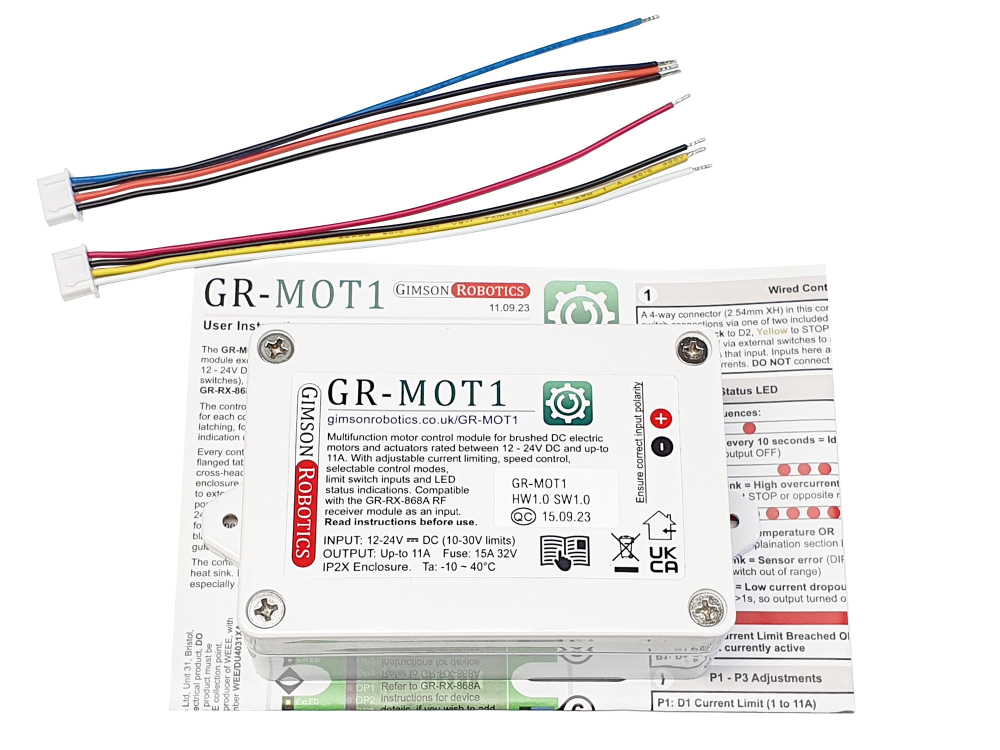
LED status indications
A Red status LED, visible out the side of the enclosure via a translucent light guide, provides indication of various controller states, including:
Idle: 1 blink every 10s
Current limit event or STOP input: Solid ON
Limit switch: 1 x repeating blink (for 60s after each limit event)
High overcurrent: 3 x repeating blink
Fast continuous flashing: Overtemperature or overvoltage event
Voltage & overtemperature protections
Voltage: The controller monitors the input voltage and will trigger an under or over-voltage error (with hard stop) if either:
1. The supply goes above 30V, or below 10V. Or
2. From the beginning of a movement (output off), the measured supply voltage increases by more than 20% (for >10ms) during the cycle (including during deceleration).
Feature #2 is intended to reduce the risk of damage to a power source if it is unable to handle regenerative currents from the controller. If either 1 or 2 triggers, output is stopped and disabled for at least 10 seconds, with fast-flash indication.
Temperature: An on-board temperature sensor is configured to trigger and stop the output at ~75°C, and to reset once the temperature falls below ~60°C. The overtemperature state uses the same LED indication as the voltage error state.
Optional remote receiver: GR-RX-868A
With the addition of a plug-in receiver module (part reference
GR-RX-868A) it is possible to remotely operate the GR-MOT1 either using many 868MHz remote transmitter options from
RF Solutions (including the 2 button
FOBBER-8T2, which we
offer as a stock option), or with our own stylish
GR-TX-868A hand-held remote with magnetic wall holder. The remote logic (momentary or latching) may be set independently of the wired logic, and remote and wired inputs may be used in tandem (we would recommend that most remotely operated systems also use the wired control inputs, as a back-up or override).
If you are looking to pair additional remotes to the GR-RX-868A receiver then bear in mind that for the GR-MOT1,
receiver OP2 = D1, OP3 = STOP and OP4 = D2. Therefore, if you want to program a remote to control direction D1 you need to wait for two receiver flashes before pressing the remote button to pair it to that output, and if you want another button to control D2 wait for 4 receiver flashes before pressing the remote button. See the
receiver instructions '
Pairing Process' subheading, for more details.
Technical Information
Part ID
Without remote module: GR-MOT1. With remote module: GR-MOT1-RX
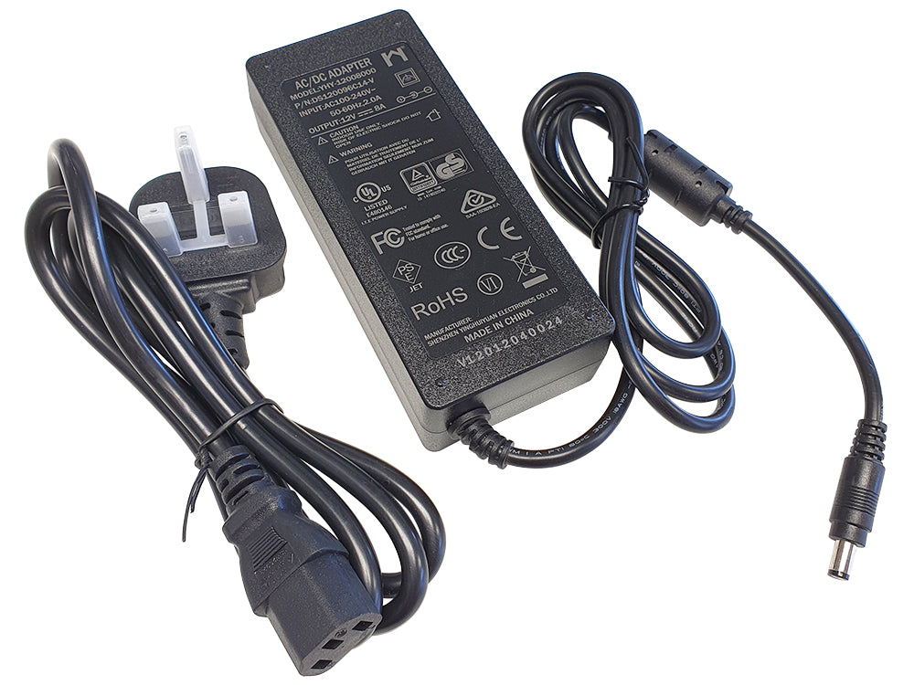
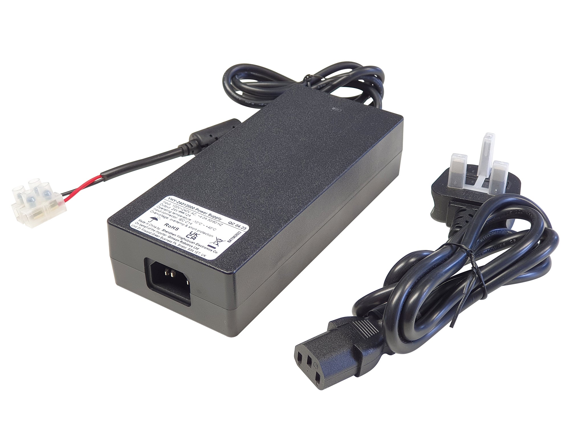
Operating Voltage
12 - 24V DC (limits 10-30V)
Output
19.6kHz PWM output, up-to 11A maximum sustained load
Idle current
<9mA (GR-MOT1, no receiver, LED OFF), up-to <35mA (GR-MOT1-RX with LED ON)
Wired Input Logic
HIGH (ON) 3.3-12V, LOW (OFF) 0-1V
Accelerations
800ms Acceleration, 500ms or 0ms Decel (see Regen mode select)
Ambient Temperature
-10°C ~ 40°C (with on-board overtemperature cut-off above 75°C)
Enclosure Details
100 x 68 x 40mm rectangular body, flanged tabs at either end with 3.5mm diameter mounting holes (overall length 125mm over flanges). Constructed from ANC160 flame retardant ABS. Be aware that this enclosure is not sealed and has not been IP tested, the device should be protected from water or extreme humidity environments
Device Standards
EMC: EN 55014-1:2021, EN 55014-2:2021
Electrical Safety: EN 62368-1:2020
RoHS 2015/863
If you are unsure about the suitability of this device for your application, or if you have any questions about bulk ordering or customisations,
please contact us.
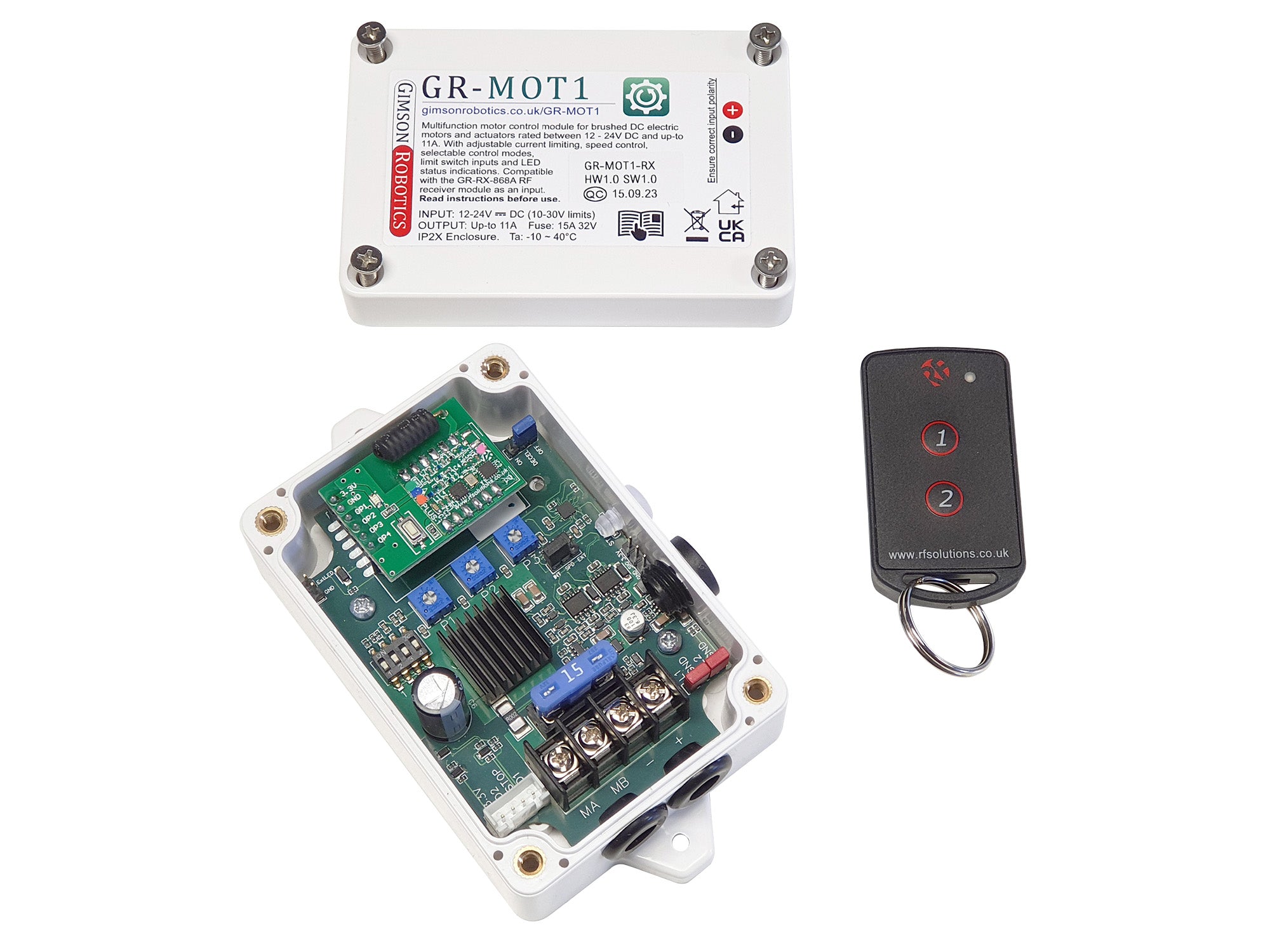
 GR-MOT1-RX with FOBBER-8T2 Remote
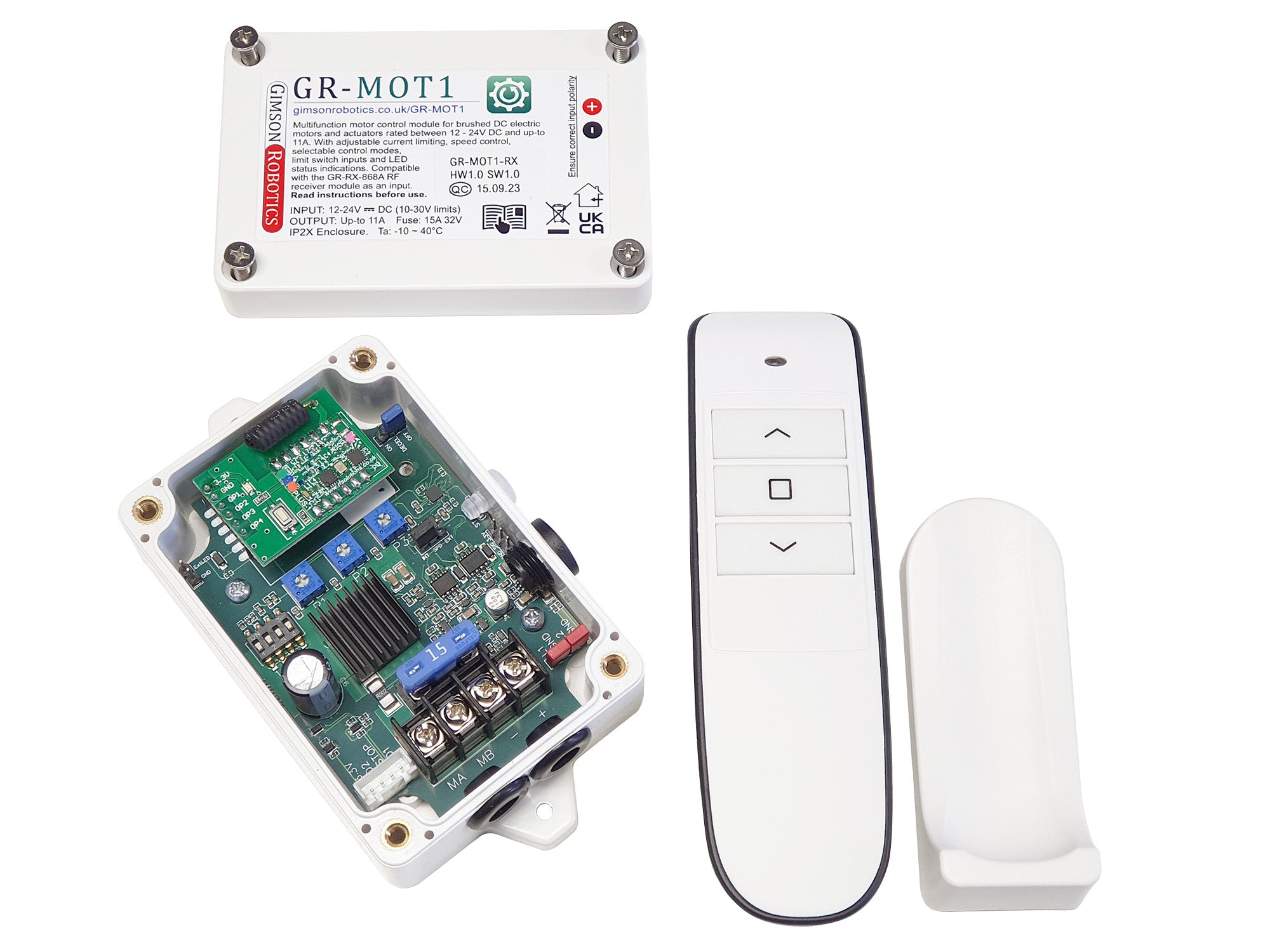
 GR-MOT1-RX with GR-TX-868A Hand-Held Remote