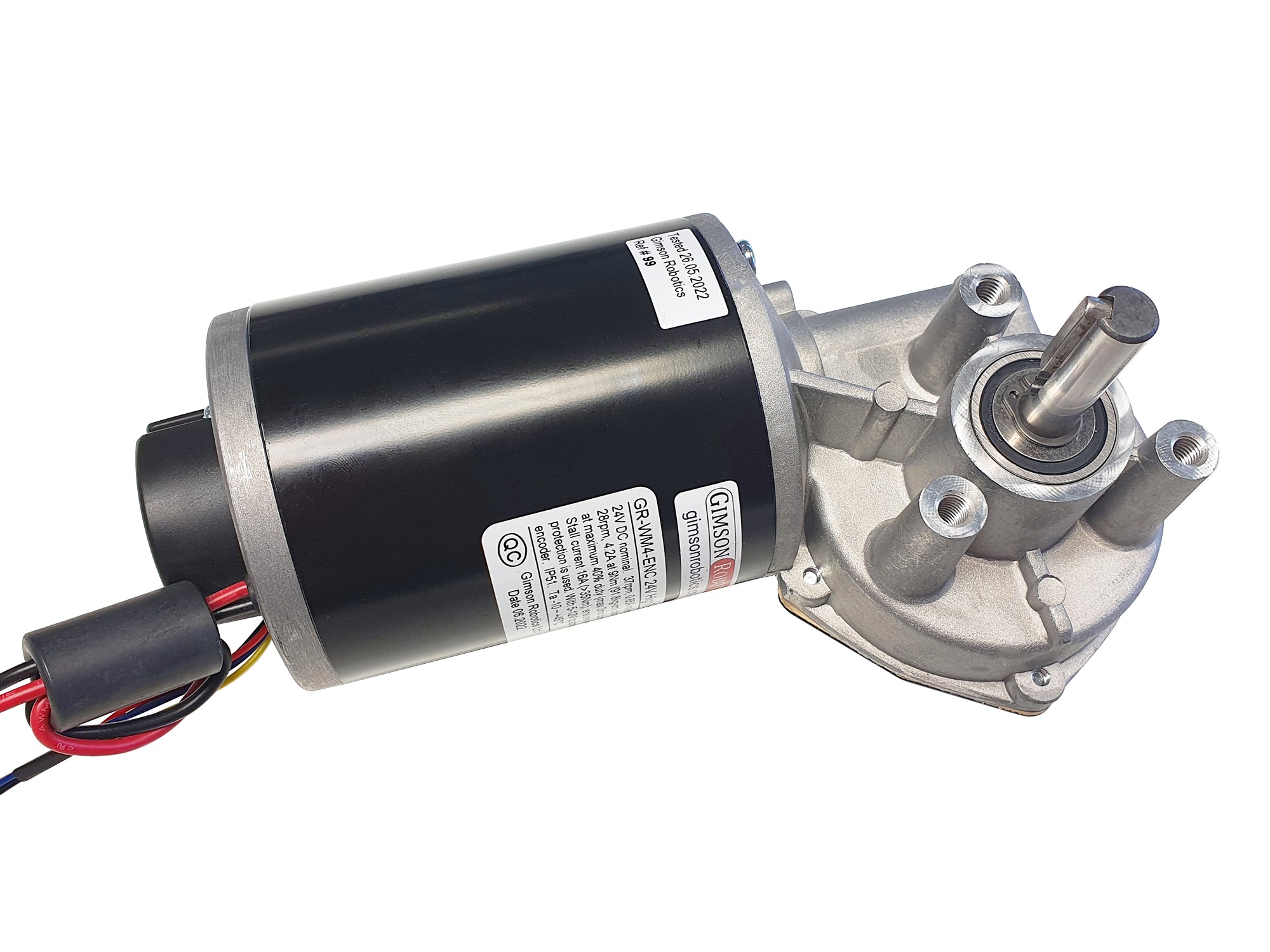
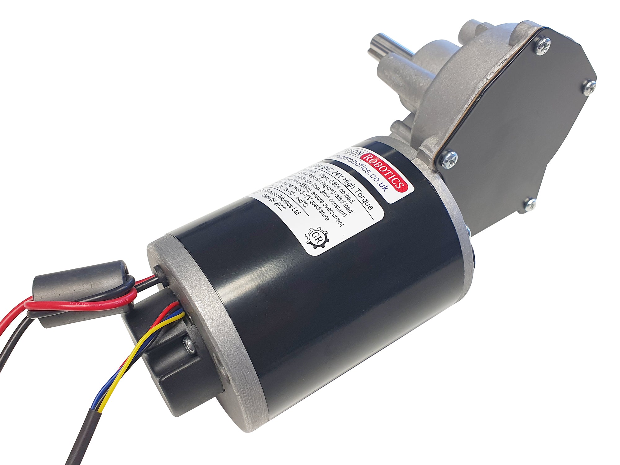
The GR-WM4-ENC is a compact and low-noise solution for high-torque intermittent load applications. Potential applications include electric door openers, winches, turntables, special effects (theatre, TV), and home automation.
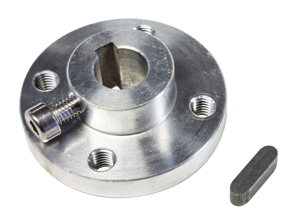
The body houses a steel and bronze single-stage gear reduction, within a cast aluminium gearbox. The 10mm diameter 35mm long steel output shaft, with a 4mm groove, provides a convenient mounting profile which is compatible with many readily available couplers and bearings, including our 10mm mounting hubs. The motor is mounted via three M6 tapped holes, on a 50.8mm PCD about the output shaft (see drawing further down this page).
When mounting loads on to the output shaft bear in mind that larger-sized radial loads (those acting perpendicular to the shaft) should be supported by additional bearing/bushings, to avoid putting too much stress on the gearbox and shaft (which is rated up to an 8Nm radial load). For example a wheel with a centreline at the end of the shaft ought to be supported by a bearing on the opposite side too, if the load on the wheel is expected to be greater than 20kg.
Inside, the motor uses both inductors and capacitors to minimise radiated electrical noise, as well as a ferrite ring on the motor wires, all intended to save future headaches when incorporating the motor into products that need to meet EMC standards.
CAD models are available, please contact us for a copy.
Integrated Encoder
The motor has a hall-sensor based quadrature encoder mounted to its rear, inside the black plastic rear cover. The encoder is not required for operation (and won't affect operation if left disconected), but for many projects it provides very useful feedback of the speed, and relative position, of the motor. It is accessed via the thinner Red, Black, Blue and Yellow wires. Positive power for the encoder (<10mA) should be provided to the Red lead (+5V VCC), and Black should be connected to ground/GND. Ensure that the correct polarity connection is made to these wires.
It has a dual-channel output (channel A Blue lead, Channel B Yellow lead), with 6 complete pulses per channel, per rotation of the motor itself (12 PPR across both channels); or 60 x 6 = 360 pulses, per channel, of the output shaft given the 60:1 gearbox ratio. One of the channels is out of phase with the other, as such it is possible to tell both the speed (from pulse frequency) and direction (by reading the pulses of one channel and comparing it to the other) of the motor. The nature of the signals that are generated is illustrated below. Given the approximate no-load motor speed of 2220rpm for the 24V motor (when at 24V) the pulse frequency may be up to 2220 / 60 x 12 = 444Hz across both channels, if counting complete pulses, or as much as 888Hz if your controller is counting pulse edges across both channels.
User Advice
This motor operates like any other DC motor and so may be used at voltages other than the nominal 24V with changed operating characteristics (please be aware that the warranty does not cover operation above 24V, which is likely to shorten the lifespan). Reducing the voltage reaching the motor will decrease the output speed and the torque, while increasing the voltage will increase the speed and the torque (torque is directly related to current).
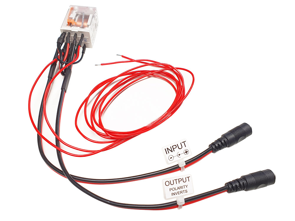
To change the direction of rotation swap the polarity of the power to the motor contacts (invert positive and negative). This is usually done via a control switch or controller, for example our rocker switch harness or GR-MOT1 control units.
You should fit circuit protection to protect both the motor from stalling/overheating and your power source from overload. At a minimum this would be a fuse in series with a motor, but you might want to fit a more sophisticated protection device such as the GR-SENS instead, for adjustable protection.
Make sure to read the performance tables for your selected gearbox option under 'Technical Details' below, so that you have an understanding of the torque, current and speed that you can expect from the motor. If you're unsure about selecting the appropriate motor for the task please send any details of your application that you have over to us and we'll talk through the options.
Motor Dimensions
Please see drawing below. CAD models are available, please contact us for a copy.

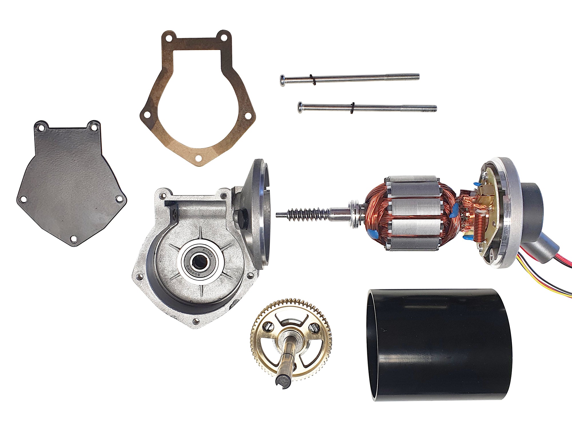
Construction Detail
Mounting
3 x M6 tapped holes, each ~18mm deep. PCD 50.8mm (around output shaft).
Overall size
Approximately 199mm long, 115mm tall, 79mm deep (excluding output shaft).
Body material
Cast aluminium gearbox housing with steel motor casing.
Gearbox type
Single-stage worm transmission with 40Cr steel worm and bronze worm-wheel.
Maximum gearbox torque
Up-to 222kg-cm (21.8Nm), as limited by the motor shaft bearings. Be aware that at higher voltages the motor itself is easily able to generate greater torque than this (see table below), so ensure that there is overcurrent protection, or a mechanical clutch, in place to prevent it exceeding this mechanical rating, if there is a danger that your application may go beyond it
Operating temperature
Ambient: -5°C ~ +45°C. The motor is not suitable for unprotected outdoor use. Motor insulation class F (up-to 155°C hot spot temperature).
Shaft type
10mm diameter (h7) by 35mm long.
Features a 26mm long, 4mm wide and 2.5mm deep rectangular keyway.
Shaft support
Dual deep-groove 6000RS (10mm ID) ball bearings
Radial load rating
Up-to 82kg-cm (8Nm). Equivalent to approximately 23kg across the end of the shaft
Weight
1810g, excluding optional lead/connector additions.
Operating characteristics (values at output from gearbox)
No-load speed
37rpm
18rpm
No-load current
0.85A
0.75A
Continuous rated torque, speed (maximum 40% duty, up-to 2-minutes continuous)
91.8kg-cm, 28rpm
45.9kg-cm, 14rpm
Rated load current
4.2A
2.5A
Rated output power
26W
6.6W
Max. power torque, speed
204kg-cm, 18rpm
102kg-cm, 9rpm
Max. power current
8.4A
4.4A
Stall torque
(408kg-cm)
204kg-cm
Current for maximum rated gearbox load
9A
-
The maximum rated output torque of the gearbox is 222kg-cm (limited by motor bearings). Ensure that the supplied current is limited to below the value highlighted in red, to prevent the motor from damaging itself by exceeding this maximum load.
Please be aware that some of the values above are extrapolated from other measurements and it's normal for there to be a small degree of variance from motor to motor, you should allow for a safety factor of at least 10% above/below the given values when designing for your application. Be sure that any equipment that you use with the motor (power source and controller) is capable of handling the currents that the motor may demand, whilst also being able to limit the current to protect the motor in the event of the load increasing unexpectedly.